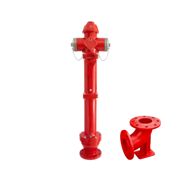
Fire Hydrants
| TECHNICAL SPECIFICATIONS | |
| Diameter | DN80→DN100 |
| Pressure | PN10 – 16 |
| Height | Short, Medium, Long |
| Design | TS EN 14384 |
| Connection | EN 1092-2 / ISO 7005-2 – Flanged |
| Tests | TS EN 14384 |
| Corrosion Protection | Electrostatic Powder Coating |
FEATURES
The hydrant water intake nozzles are positioned above ground level.
The products are designed and manufactured in accordance with the EN 14384 standard.
It offers the ability to quickly and conveniently put into operation.
The hydrant valve is opened and closed by turning the control lever located at the top clockwise using the hydrant key.
It can be manufactured in different L sizes and various length options depending on the need.
After use, any water remaining in the hydrant is automatically drained via a check valve.
To prevent freezing, hydrants should be kept closed in cold weather conditions. This allows the water inside to be drained using the valves.
During installation, care should be taken to position the drain valves so that water can drain freely.
The body material is spheroidal graphite cast iron, while the control shaft is made of stainless steel.
For ease of maintenance and repair, installation is recommended with filling using materials such as gravel.
All body and cover plate parts are protected with a powder epoxy coating applied using the fusion method.
Before installation, the pipe line should be cleaned with pressurized water or air; additionally, a dirt trap should be installed on the water inlet line.
There are two water intake ports on the hydrant, and their covers are made of aluminum.
During the opening process, it is recommended to remove one of the aluminum caps to release the air that has accumulated inside.
APPLICATION AREAS
Fire suppression systems and infrastructure lines
Get in Touch
You can contact us through the following methods.
- Phone
0545 196 86 44
info@smsgirisim.com
- Address